Sample & Hold (S&H) Circuits
Introduction
Sample & Hold (S&H) circuits are a kind of circuit which is widely used in analogue and mixed-signal circuits and they are also referred to as Track & Hold circuits. The basic function of S&H circuits is to “sample an analogue signal and store its value for the length of time”, so it is said that it converts a continuous-time signal to a discrete-time signal.
Some performance metrics need to be known:
- Drop rate: characterises a slow change in output voltage
- Uncertainty: a result of clock jitter, causes the difference in the effective sampling time between cycles
- Sampling pedestal or hold step: error between the sampling value and the holding value, normally caused by the charge injection or insufficient sampling time.
Circuits
Basic Circuits
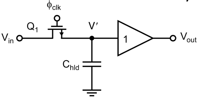
The most basic S&H circuit is composed of a switch and a holding capacitor followed by a buffer, shown below. The biggest problem with this is the error caused by charge injection. The charge injection causes an error on the holding capacitor(even changing with $V_{in}$) and negative glitches, if the source impedance of $V_{in}$ is small.
Of course, there are some methods to minimise these effect, one using trasmission gates, another dummy switches.
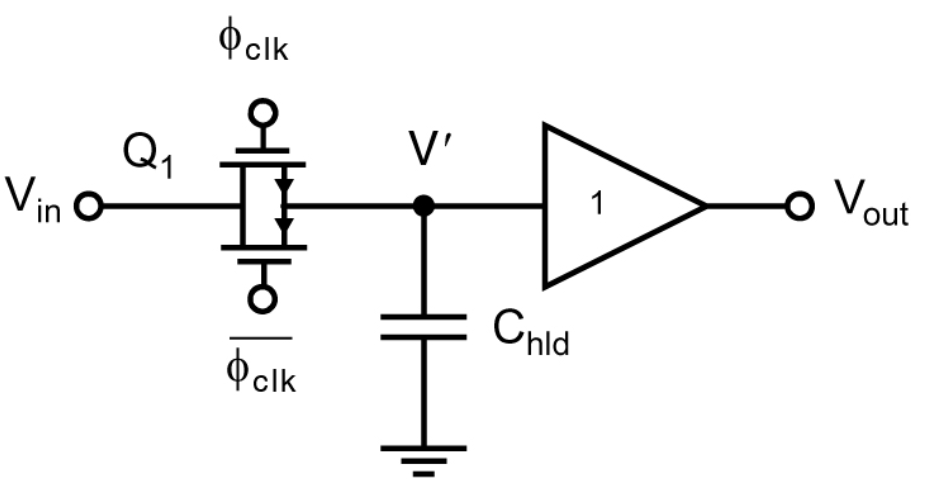
Transmission gate switches Ideally, pMOS and nMOS can absorb the channel charge of each other, and have no effect on the holding voltage. However, there are some practical factors make it impossible:
- The turn-off time of the transistors are signal-dependent because of the changing source voltage, which means n-switch and p-switch toggle at different moment.
- The channel charge of nMOS and pMOS are also signal-dependent. The higher $V_{GS}$ magnitude, the more channel charge it will be, and a part of the extra charge will transfer to the holding capacitor.
Dummy switches Another way to mitigate the error caused by the charge injection is adding a dummy switch whihc is half size of the size of $Q_1$, shown as below.
Although this way doesn’t have the drawbacks like T-gate switches and it can even suppress the effect of clock feedthrough, the non-linear ON-resistance still limits its application.
Advanced Circuits
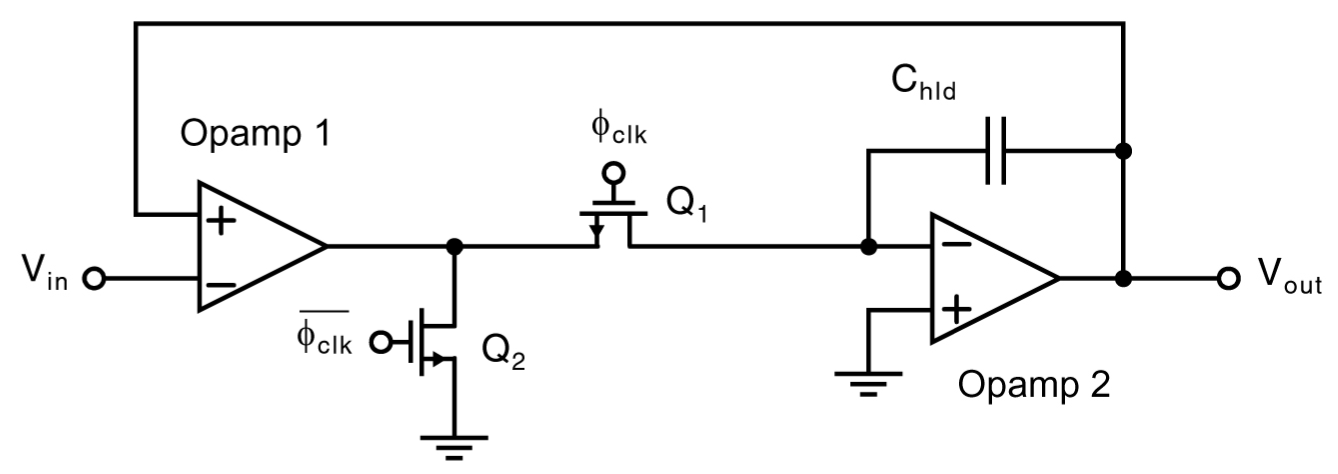
Some advanced circuits include an Op-amp in the feedback loop to increase the input impedance of S&H circuits. In addition, the offset of the buffer is suppressed by the gain of the Op-amp, so using a source follower is a good choice. A typical circuit is shown below.
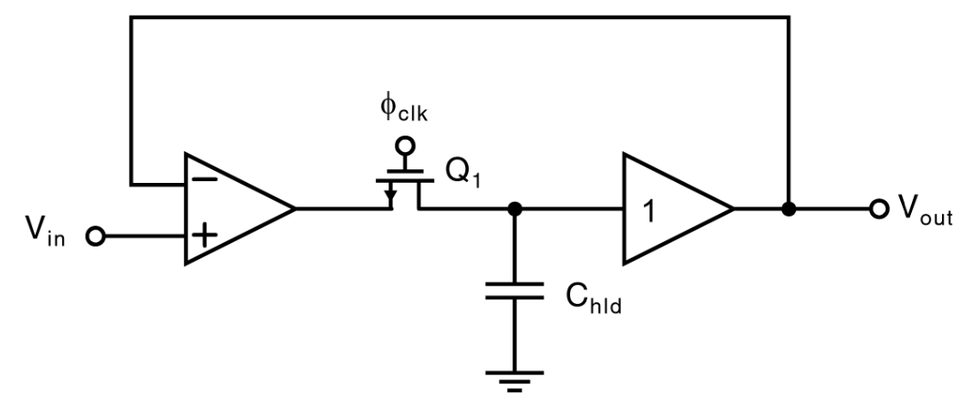
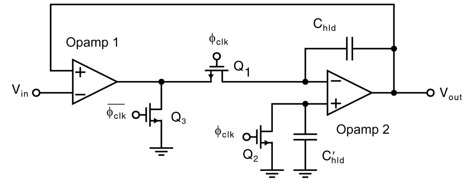
However, this circuit has a fatal drawback: during the holding process, $Q_1$ cut off the feedback loop which make the Op-amp be saturated. After that, when the circuit samples in the next cycle, some extra time is needed to make the Op-amp slew back. The good news is we can add some switches to prevent this, and like the schematic shown below, the Op-amp operates in closed-loop at all time.
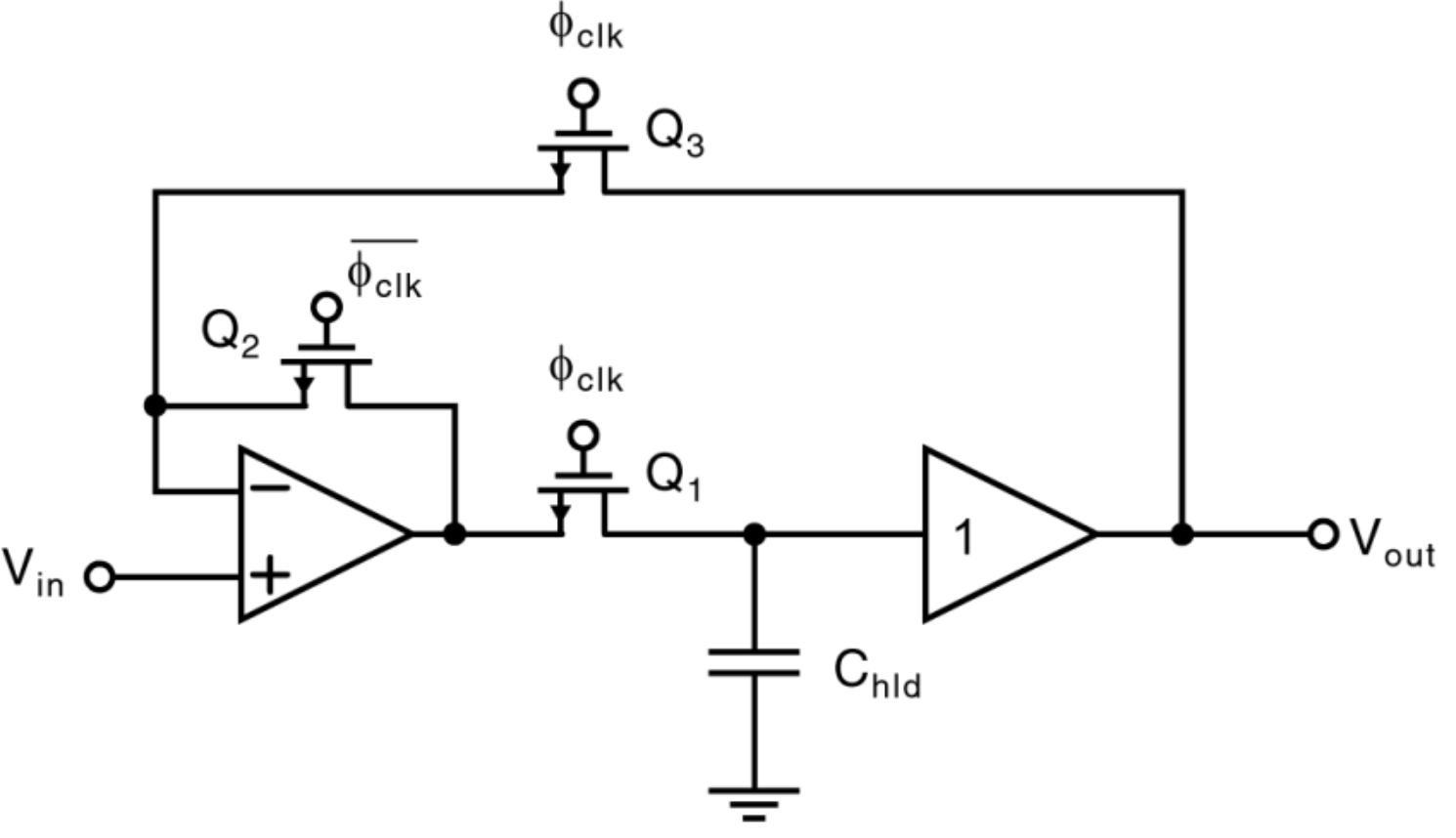
Actually, the channel charge of $Q_1$ is signal-dependent which make the injected-charge signal-dependent. To fixed this, a new circuit is proposed. Right now, the voltage of both sides of $Q_1$ is signal-independent and therefore, it only causes a fixed DC error voltage, which can be easily fixed.
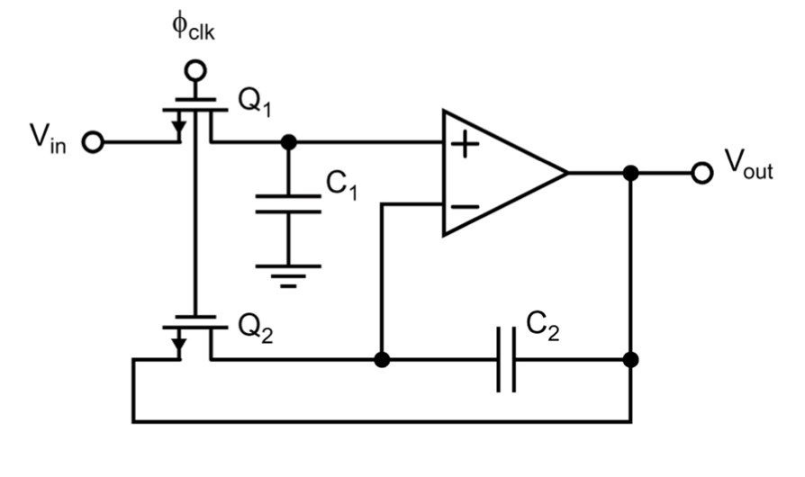
One way to fix this is matching the injected-error to both terminals of the Op-amp, shown as below:
Another way to relax the process from charge injection is shown as below and the two switches are controlled by the same controllomg signal.
Reference
https://www.d.umn.edu/~htang/ECE5211_doc_files/ECE5211_files/Chapter11.pdf
https://www.uio.no/studier/emner/matnat/ifi/IN5180/h21/timeplan/inf5180_sample_hold_h21.pdf
Copyright Statement
This article is an Original Work of Bohao, if reprinted, please indicate the source: http:/merenguelee.github.io/2023/12/17/Sample-and-Hold-Circuits/