The Speed of the Op-amp
In Mixed-signal design, or to be concrete, in switched-capacitor circuit design, a scene is often encountered: the op-amp needs to charge a certain capacitor. In this scenario, the output waveform is normally like this:
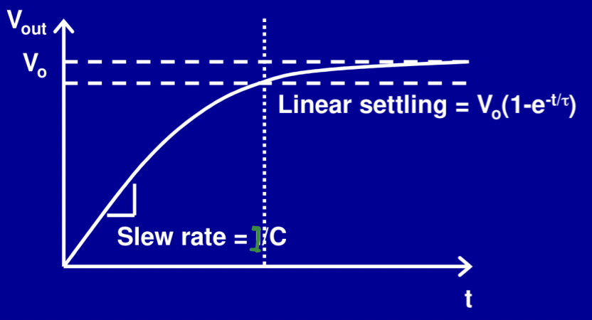
The voltage of the capacitor is charged to a target value, and the speed of charging will determine a kind of error called “settling error”. Normally, the speed of this process is determined by the designed op-amp; the faster the op-amp is, the less the error will be. From the output voltage, it can also be concluded that this process has two stages: one slewing stage, and another linear settling stage. At the slewing stage, the output voltage decreases linearly since the output current is constant but at the linear settling stage, the capacitor is charged with the time constant $\tau$.
The charging speed of the first stage is determined by the large-signal bandwidth of the amplifier, which is also called the slew rate, while the second is determined by the small-signal bandwidth, also known as the gain-bandwidth of the amplifier.
Large-signal Bandwidth
From the figure given before, the slope of the output voltage is determined by the slew rate of the designed op-amp, and the expected slew rate can be designed by the bias current of the circuit. For an amplifier which is charging a capacitor, the slew rate can be expressed as
\[S = \left(\frac{d V_o}{dt} \right)_{max} = \frac{I_{o,max}}{C},\]which means the expected slew rate and the loading capacitor will determine the maximum output current (bias current) of the amplifier. In a general scenario, the amplifier charges the capacitor with a sinusoid voltage (always configured as a voltage buffer form), which means the output voltage is $V_o = V_{max} sin(\omega t)$. The slew rate is then given by:
\[S = \left(\frac{d V_o}{dt} \right)_{max} = \omega V_{o,max} = 2 \pi f\ V_{max},\]where $V_{max}$ is the amplitude of the output signal. In the end, the large-signal bandwidth can be defined as:
\[f = \frac{S}{2 \pi \ V_{max}}.\]Small-signal Bandwidth
For consideration of the small-signal bandwidth, let’s first begin with a simple feedback system, shown below.
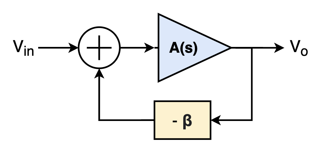
Assuming the amplifier is a single pole system, whose transfer function is given by:
\[A(s) = \frac{A_o}{1+ s/\omega_o},\]where $\omega_o$ is the pole of the system, and $A_o$ is the open-loop gain of the amplifier. Therefore, the transfer function from the input to the output is expressed as:
\[H(s) = \frac{A(s)}{1+ \beta A(s)} = \frac{A_o}{1+\beta A_o} \frac{1}{1+s/[(1+\beta A_o)\cdot \omega_o]},\]and then the time constant is given by:
\[\tau = \frac{1}{(1+\beta A_o)\cdot \omega_o} \approx \frac{1}{\beta A_o \omega_o} = \frac{1}{\beta\cdot GBW},\]where $GBW$ is the gain-bandwidth of the amplifier. For a step input signal, which is $V_{in} = V_d \cdot u(t)$, the output would be like:
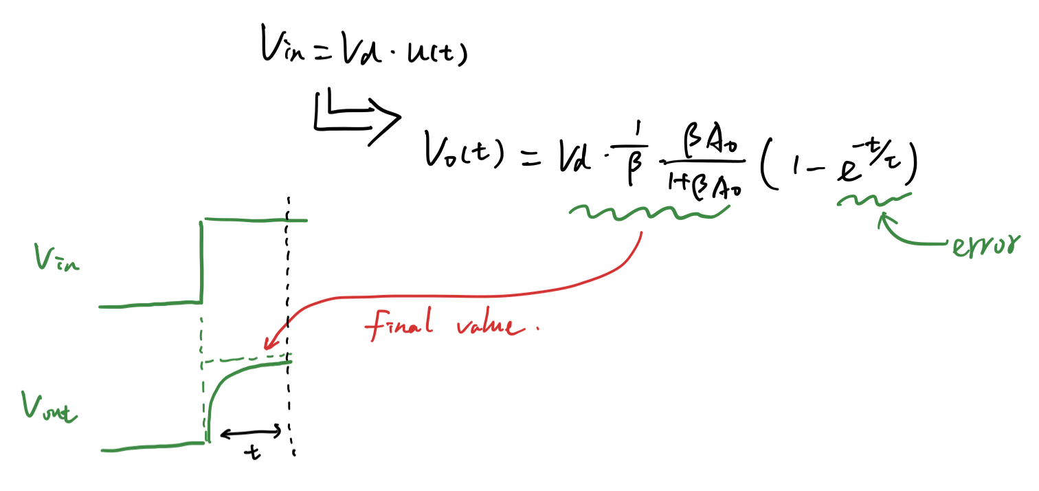
In other words, the speed of charging at the linear setttling stage is determined by the gain-bandwidth of the amplifier. Besides, as given in the figure, if the loop gain is extremely high, the final value of the output would be $V_d/\beta$.
Reference
https://zhuanlan.zhihu.com/p/510377997
https://www.edn.com/slew-rate-the-op-amp-speed-limit/
Copyright Statement
This article is an Original Work of Bohao, if reprinted, please indicate the source: http:/merenguelee.github.io/2023/09/11/The-Speed-of-the-Op-amp/