Learn Band-gap Reference from scratch
Band-gap reference (BGR) is a voltage reference that is independent of temperature and power supply, or it can be seen as an “ideal” voltage source in terms of robustness to these external conditions. The basic idea is combining two voltage with opposite temperature characteristics. In band-gap reference, these two voltages are $V_{BE}$ of the BJT and the difference of the $V_{BE}$ of two different BJTs.
$V_{BE}$ Temperature Dependence
It is known that the collector current of BJT is
\[I_C = I_S\cdot e^{(V_{BE}/V_T)}\], so the voltage across the Base terminal and Emitter is:
\[V_{BE} = V_T\ ln(I_C/I_S)\]where $I_S$ is determined by the area of the Emitter.
Therefore, the dependence of the $V_{BE}$ on temperature can be derived:
\(\frac{\partial V_{BE}}{\partial T} = \frac{\partial V_T}{\partial T}ln(I_C/I_S) - \frac{V_T}{I_S}\frac{\partial I_S}{\partial T}\) which means $V_{BE}$ is negatively proportional to absolute temperature (NTAT). Assuming $I_C$ as constant, ${\partial V_{BE}}/{\partial T}$ will be around $-1.5\ mV/K$.
$V_T$ Reference Technique
This reference is generated by the structure below, where $Q_2$ is n-times the size of $Q_1$, so $I_{S2} = nI_{S1}$. Because the current mirror forces the current of two branches to be the same, the voltage across the resistor will be:
\[I_{C2} R= V_T\cdot ln(I_{C1}/I_{S1})-V_T\cdot ln(I_{C2}/I_{S2}) = V_T\cdot ln[\frac{I_{C1}I_{S2}}{I_{C2}I_{S1}}] = V_T\cdot ln(n) = \frac{kT}{q}ln(n)\]and this voltage is proportional to the temperature, $\partial V_R / \partial T = (k/q)\ ln(n)$, where $k/q \approx 0.087\ mV/T$.
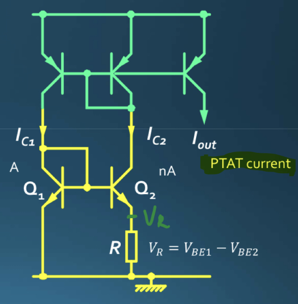
Thus, this circuit will generate a current that is proportional to absolute temperature(PTAT).
Band-gap Reference
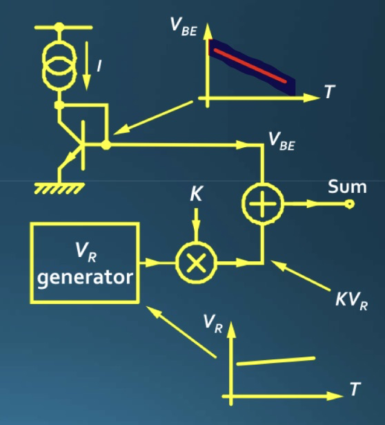
So far, we have gained two voltage sources with opposite temperature characteristics, and theoretically, after combining them with certain factors, a voltage source which is independent of the temperature can be get.
Circuit 1
For the circuit shown below, $R_1 = R_2$ and $Q_2$ is n-times the size of $Q_1$. Because of the “virtual short” of op-amp’s two input terminals, $V_{R1} = V_{R2}$ and hence $I_1 = I_2$.
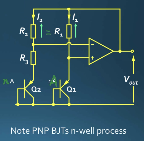
It also can be concluded that the voltage across $R_3$ is:
\[V_{R3} = V_T\ ln(\frac{I_1 I_{S2}}{I_2I_{S1}})\]so
\[V_{R1} = V_{R2} = \frac{R_2}{R_3}\ V_{R3} = \frac{R_2}{R_3}\ V_T\ ln(n)\]Hence the output voltage is:
\[V_{out} = V_{BE1} + V_{R1} = V_{BE1} + \frac{R_2}{R_3}\ V_T\ ln(n)\]Once $(R_2/R_3)\cdot ln(n) \approx 17.2$, the temperature dependence of the output voltage can be cancelled out, and this temperature-independent voltage is around $1.25\ V$.
Circuit 2
A more intuitive circuit is shown below. With $V_X = V_Y$, the voltage across $R_1$ can be concluded as $V_{R1} = V_T\ ln(n)$, and this will generate a PTAT current through $R_1$ and $R_2$ mirrored by $M_5$. Therefore, the output voltage will be:
\[V_{out} = V_{BE3} + \frac{R_2}{R_1}\ V_T\ ln(n)\]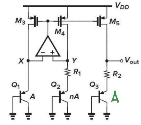
After observing the form of the output of these two circuits, it is clear that the temp coefficients of the resistors can also be cancelled out in such methods.
Temperature Dependence
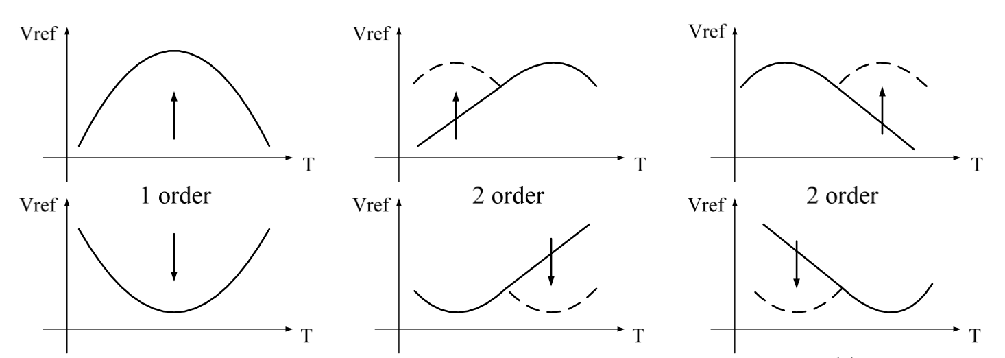
The temperature dependence of the BGR can be evaluated by the curvature of its temperature characteristics curve (the unit is ppm, standing for parts per million):
\[T_{BGR} = \frac{V_{max}-V_{min}}{V_{nom}(T_{max} - T_{min})} \times 10^6\]Also, this curvature can be compensated by higher-order GBR.
Copyright Statement
This article is an Original Work of Bohao, if reprinted, please indicate the source: http:/merenguelee.github.io/2023/07/23/Learn-Band-gap-Reference-from-scratch/