Understand the Noise-Shaping
From the beginning…
The Noise-Shaping(NS) term is quite important for the Mixed-signal designer and this blog is also the note when I learnt and designed an Oversampling Delta-Sigma Modulator(DSM).
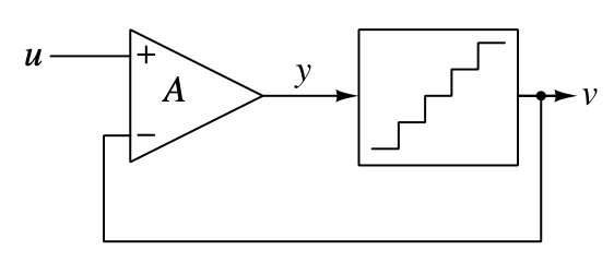
Let’s first start with a basic negative feedback system, shown below, which is composed of a amplifier and a quantiser.
The quantiser can be simply modelled as the subtraction of the quantisation noise, like this:
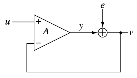
Therefore, the output of the system will be:
\[v = (\frac{A}{1+A})u + (\frac{1}{1+A})e\ .\]If the model makes sense, the quantisation noise will never affect the output of the system when the gain of the amplifier $A\rightarrow \infty$. However, this expectation will not be realised because the quantisation process needs time to complete, so inserting a delay in the feedback path can more accurately mimic the real system, shown below.
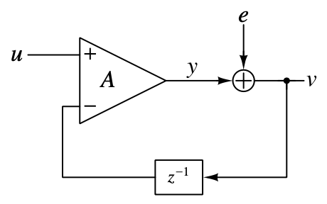
In this case, the output will be:
\[V(z) = (\frac{A}{1+Az^{-1}})\ U(z) + (\frac{1}{1+Az^{-1}})\ E(z)\]where $U(z)$ is the input signal, and the multiplier of it is the Signal Transfer Function(STF). Also, the multiplier of $E(z)$ is the Noise Transfer Function(NTF). STF and NTF have the same denominator which is the characteristic polynomial of the system as well. As $A\rightarrow \infty$, the STF approaches unity and the NTF tends to zero[1], and that is what we expected. So… that’s the end?
Definitely not, because when we consider the stability of the system(the position of the pole: $z = -A$), it can be seen that the system will only be stable when the gain of the difference amplifier is less than 1, shown in the below figure.
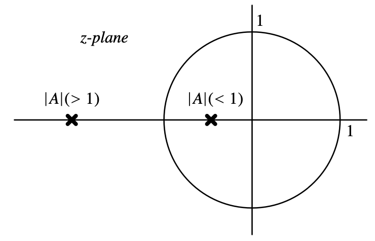
Sorry, what? The conclusions seem to be contradictory, and the system is unrealisable, so we need some modifications. Let’s recall the expression of the output and the block diagram, what do they tell us? It’s not easy to spot that the gain of the amplifier is $A$ at all frequencies. Actually, we don’t need it to be really high at all frequencies, and what we expect the amplifier is to only remain high at low frequencies because it’s an oversampling system.
And after refreshing our requirements, a component comes to my mind — An Integrator! The integrator has a infinite low-frequency gain and the gain is relatively low at higher frequencies. By replacing, the system will be:
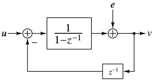
So the transfer function of the resulting system is:
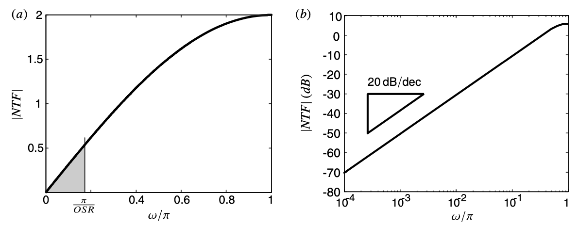
\[V(z) = U(z) + (1-z^{-1})\ E(z)\]which means the STF is unity and the NTF, $(1-z^{-1})$ , is a first-order high pass response with a zero of transmission at dc ($\omega = 0$ or, $z = 1$). The NTF also shows that the quantisation error should be zero at low frequency, and the response of the NTF is also shown below, which is shaped.
Apart from that…
One thing should be noticed is that: although the in-band noise(after filtering) decrease, the total quantisation noise in the output is actually increased compared with the noise power introduced by the quantiser (which is $(\Delta ^2 / 12)$). The total quantisation noise power over the entire band ($[0,\pi]$) is $(2\cdot\Delta ^2 / 12)$, which is two times than the original. This effect can be easily seen in time domain, shown in the following figure. It can be seen that the ouput of the noise-shaping version contains many transitions between levels and the quantisition noise is greatly suppressed.
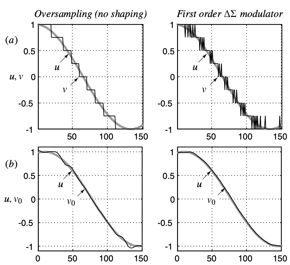
This actually makes sense because the gain of the quantisation nosie at high frequencies ($\omega = \pi$, or $z=-1$) is
\[(1-z^{-1})|_{z=-1} = 2\]rather than 1 for the one without noise-shaping.
Reference
[1] Pavan S, Schreier R, Temes G C. Understanding delta-sigma data converters[M]. John Wiley & Sons, 2017.
Copyright Statement
This article is an Original Work of Bohao, if reprinted, please indicate the source: http:/merenguelee.github.io/2023/06/11/Understand-the-Noise-Shaping/