How to understand MILLER’S Theorem
Miller’s theorem
To begin with, a brief introduction to Miller’s theorem is necessary.
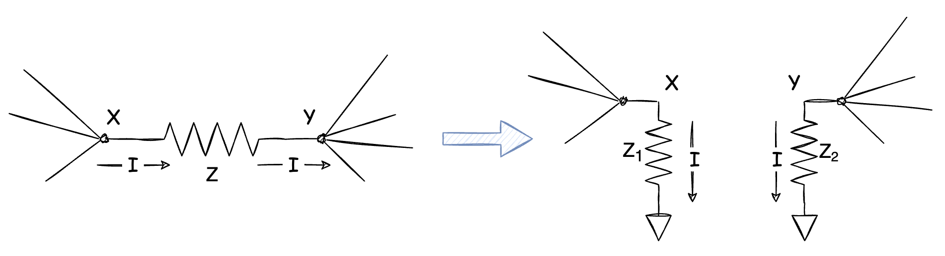
In short, according to the diagram above, in order to make the current flow in/out of those two nods (X & Y) unchanged. the equations can be get:
\[Z_1 = \frac{Z}{1-\frac{V_Y}{V_X}} \\ Z_2 = \frac{Z}{1-\frac{V_X}{V_Y}}\]which is Miller’s Theorem.
Understanding
How to measure the input impedance
From above, we could say that Miller’s Theorem inverts a “floating” impedance to the input impedance of nodes X and Y, so how do we usually measure the input impedance? Usually, we choose this way below.
- Input a step voltage ($\Delta V$) into the testing node.
- Measure the charge offered by this voltage source [$\Delta Q = \Delta V \cdot C$], and then the input impedance of this node can be get.
In this case (a capacitive impedance)
This diagram shows a very common scenario that a capacitor is connected between the input and output of an amplifier.
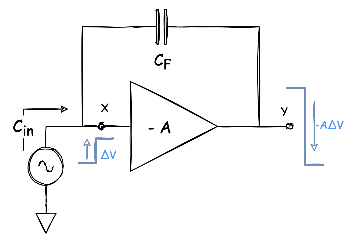
Node X: $\Delta V$;
Node Y: $- A \cdot \Delta V$.
$\Delta Q$ on $C_F$ : $(1+A) \cdot \Delta V \cdot C_F$, and that applies to the input capacitance:
\[C_{in} = (1+A) \cdot C_F\]Something Interesting
If we look back to the introduction to Miller’s Theorem, there is something that can be found: $Z_1 + Z_2 = Z$. If we think that not in a mathematical way, it looks like we “cut” the impedance into two pieces ($Z_1$ & $Z_2$ ) and at that “cutting point”, the voltage drops to 0, like a “virtual ground” (of course, small signal voltage, not the real voltage).
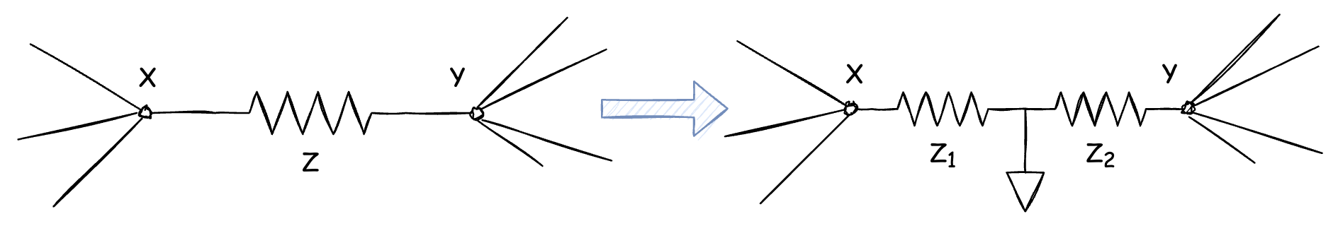
Similarly, recall the case above. $V_X$ and $V_Y$ have different polarities, and there will have a point in $C_F $whose voltage must be 0.
BTW:
The measurement of input impedance also reminds me of how we measure the resistor or “equivalent resistor” in a circuit. And before we talk about it, let’s first define what is a resistor.
what does a resistor do
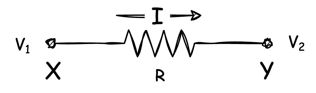
The resistor is something that impedes, and slows down, the movement of charge. When we think about a resistor below, it’s quite easy to conclude that the current across the resistor is: $I = (V_1 - V_2) / R$.
Therefore in a given time, $ t$, a charge of $Q = (V_1 - V_2) t /R$ transfers from X to Y.
Wait, what? What a commonsense! Do I need you to tell me that?
Yes, it is a commonsense, but if we think that carefully, and if we can arrange this in some other way, we can have a resistor-substitute that is quite different from the resistor we considered before. A very classic example of this is switched capacitor (shown below), and after applying this theory, we can know the equivalent resistor of this circuit is:
\[R_{eq} = \frac{1}{C_1 \cdot F_{CLK}}\]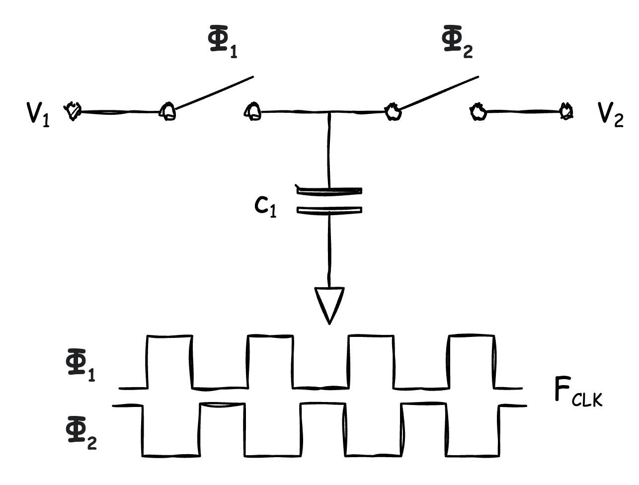
Reference
[1] Razavi B. Design of analog CMOS integrated circuits[M].
Copyright Statement
This article is an Original Work of Bohao, if reprinted, please indicate the source: http:/merenguelee.github.io/2023/02/17/How-to-understand-Miller-Theorem/